What happens when an AI rack has to make room for its own cooling pump?
Gates announced a compact pump for in-rack liquid cooling. Here’s how to read its flow claim, compare rack layouts, and find out what each server will actually receive.
Imagine expanding a room of air-cooled servers with one liquid-cooled AI rack. The racks on either side still have to run. The new servers need a supply of coolant, a way to deliver enough of it to every server, and somewhere to send the heat they put into it. Putting the coolant distribution unit in the new rack can keep the server-side loop close to the equipment. It also puts the pump, connections, and service access in the same space the team has to allocate to servers.
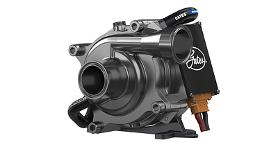
On November 12, 2026, Gates announced the ThermalCool 2100SS, a 4U-compatible pump for rack-mounted coolant distribution units (CDUs). Gates makes fluid-handling equipment including hoses and couplings, and the 2100SS adds active coolant circulation to that portfolio. The company invites sample requests and targets global availability in early 2027. The November announcement gives a design team something to evaluate and an expected release window. Regional lead times and the date for production orders remain open. Gates November 12 announcement and product photograph
The useful question for that first rack is how much space you save after you have accounted for the rest of the CDU, and how much coolant the most demanding server can still receive when the loop is warm, the filter is loaded, or a pump is unavailable. That is what separates a promising component specification from a cooling system you can accept.
Where the heat goes when the pump moves into the rack
A liquid-cooled server conducts heat from a chip into a cold plate mounted against it. Liquid passing through the plate takes up some of that heat. In a typical installation with a liquid-to-liquid CDU, a rack manifold splits supply flow among server branches and collects their return flow. A heat exchanger in the CDU transfers heat from that equipment-side coolant to facility water. The rack pump circulates the equipment-side coolant, and the facility still has to carry the transferred heat away. Some parts of a server can still need airflow, depending on which components the cold plates cover. Open Compute Project cold plate requirements
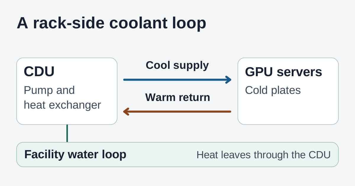
Illustration by Telli.sh. A rack-side pump circulates coolant to the cold plates, while the heat exchanger passes heat to the facility-water circuit.
A rack-level CDU can make sense for a small deployment where the facility has a suitable water connection and the team wants to qualify one rack at a time. A room with several similar racks can also evaluate a shared CDU and compare distribution distance, isolation during maintenance, and what goes offline if that unit needs service. Both architectures need a clear dividing line between the facility team and the equipment team. For example, someone needs to own the water temperature and flow available at the rack connection on a hot day, and someone needs to own the flow that reaches the last server branch.
Start the layout with the full assembly. In a 4U design, space for a pump body can be easier to find than space to connect it, route hoses around it, and pull it out. Ask to see the proposed hose bends, the location of isolation valves and filters, and the clearance a technician would use to reach them. Gates describes configurable mounting and connections, plus a motor cooled by the liquid the pump already circulates. That can help when airflow inside the enclosure is scarce. The CDU designer still has to account for the other components, the electrical feed and controls, and how much rack space the installation consumes once everything is connected. ThermalCool 2100SS specification sheet
What “up to 200 liters per minute” means for a server
Gates describes output up to 200 liters per minute at 3 bar in its announcement. The specification sheet lists maximum flow and maximum pressure differential and gives performance curves for several pump speeds. Use the curve that corresponds to the speed and conditions being evaluated. A rack’s flow depends on how much pressure it takes to move coolant through the heat exchanger, filter, hoses, connectors, manifold, and cold plates. The headline is a manufacturer figure. Gates’ announcement and spec sheet provide no measured flow at a customer’s installed rack. Gates announcement · ThermalCool 2100SS performance curves
The pump can supply different amounts of pressure at different flow rates. The loop requires more pressure as flow rises. Draw both curves on the same axes and their intersection estimates where the system will run at that pump speed. A tighter connector, a different cold plate, or a filter with more resistance can move the intersection and change the available flow. Coolant choice and operating temperature matter because they affect how readily it flows. A controls team can use the speed curves to see whether it has room to respond as conditions change and whether there is a reasonable minimum speed when fewer servers are installed.
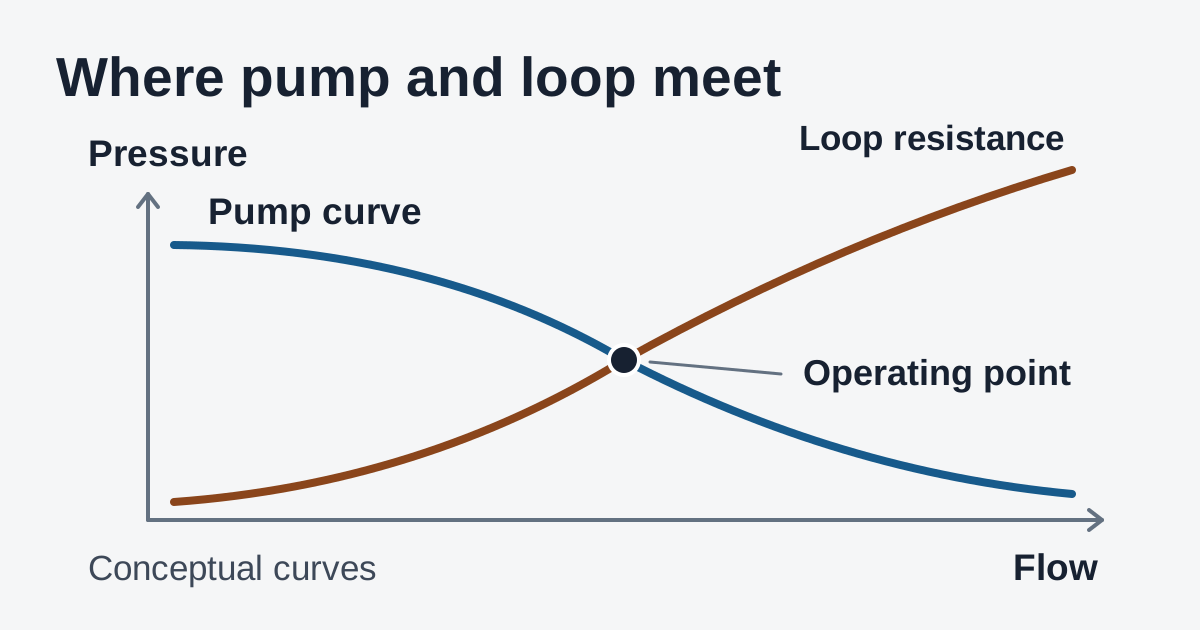
Illustration by Telli.sh. The curves show how to estimate an operating point. They represent a hypothetical loop and do not reproduce Gates performance data.
There is a second question after estimating total flow. How much goes to each server? Parallel branches share supply and return manifolds, but their paths can have different lengths and restrictions. A generous flow reading at the pump can leave a restrictive branch short of the coolant its cold plate requires. Take the server supplier’s flow and pressure-drop data for the desired coolant and temperature range. Use it to identify which branch is likely to have the least margin, then confirm the estimate by measuring branch flow or by using the server supplier’s approved validation method. The Open Compute Project’s cold plate document is a useful reference for what to request when qualifying the parts of that loop. Open Compute Project cold plate requirements
A quick heat balance can help make the numbers concrete. If a test circuit circulates 20 liters of water per minute and the water warms by 6°C on its trip through the equipment, it is carrying away roughly 8.4 kW in that measurement. This example uses approximate properties of water near room temperature. It describes the heat picked up by one hypothetical circuit. It gives no information about the temperature at any particular chip, the headroom of the heat exchanger, or the facility’s ability to reject that heat. Compare the heat balance with the server temperature readings and the conditions on the facility side to see which part of the system runs out of margin first.
What to test before a rack goes into service
Build the first evaluation around the rack you actually plan to operate. Record planned server count and the intended coolant, facility-water conditions, and the least favorable branch in the expected layout. Ask the CDU manufacturer for a complete drawing and a predicted operating point for normal service, the expected high-resistance condition, and any supported degraded mode. A production handoff is much easier when the facilities and compute teams have agreed on acceptance criteria and can read the same measurements.
| Test condition | What to watch |
|---|---|
| Representative sustained compute load | Supply and return temperatures on both sides of the CDU, plus flow and temperature at the branch expected to have the smallest margin. |
| Cold start within the design envelope | Time until circulation stabilizes, pump speed and electrical draw, and whether compute can begin only after the cooling system is ready. |
| Expected filter loading | Available flow and the trend in filter differential pressure. Check whether the service alert appears while branch flow still meets the server requirement. |
| Loss of one pump in a redundant test setup | Time to detect the fault, remaining branch flow, and the temperatures that trigger an alert, a workload reduction, or a safe shutdown. |
Use an isolated qualification loop or a staged rack with approved test loads for failure and recovery cases. The useful result of a fault test is an answer a technician can act on. If one pump becomes unavailable, for instance, the on-call team should be able to tell whether the rack can sustain its current load, whether it needs to reduce load, and how much time the measurements give it to act. Check recovery too. When the standby pump or control system comes back, the CDU should be able to show circulation is stable before normal service resumes.
Gates lists parallel operation for N+1 redundancy and CANBUS or MODBUS communication. N+1 means providing one extra unit beyond the number needed for a defined load. Verify the required flow and pressure with one pump out. Space for a second pump, its supply and control path, and the service procedure are decisions for the CDU design. So is how pump status reaches the rack monitoring system and what the rack does if data from that pump stops arriving. A pump that supports a communications protocol gives the designer an interface to work with. CDU integration determines which alarms reach the people responsible for the rack. ThermalCool 2100SS specification sheet
A facilities team comparing options should also separate limits from operating measurements. The sheet lists a 48 VDC input and a motor power specification of 2.1 kW. For electrical design, the supplier can confirm the feed, current limits, and startup behavior for the proposed assembly. For an operating cost estimate, measure actual pump and CDU electrical use at representative loads and compare configurations while holding the amount of compute work and the relevant temperatures steady. Any study of whole-room energy also needs to track server fans and facility cooling. The published specifications provide no measured energy or water savings for an installed 2100SS system. ThermalCool 2100SS specification sheet
What to ask for with a sample
For a team bringing liquid cooling into an existing room, the sample is a chance to check whether the pump helps the particular design fit. Ask for the mounting and connector drawings, usable speed curves for the intended coolant, and control documentation. Confirm what fits into the complete CDU with filters, service access, and the redundancy the rack actually needs. Ask the vendor and integrator which wetted materials and fluid conditions are supported together across the pump, hoses, seals, and cold plates. The cold plate manufacturer can provide temperature, flow, and pressure requirements for the server side. Bring those values into the same acceptance record so the rack can be tested as a system. ThermalCool 2100SS specification sheet · Open Compute Project cold plate requirements
If the assembly fits and the tightest branch has enough flow under the agreed conditions, compare the result with a shared-CDU layout or the rack design already under consideration. That comparison should cover the usable room for servers, which equipment needs to stop for service, and which measurements the team can see during a fault. Ask what support is available during sample evaluation and what changes between the sample and the planned production part. Treat early 2027 as the supplier’s target when planning procurement, with final lead time and support terms to be confirmed for the deployment region. Gates November 12 announcement
A compact pump can give the rack designer more room to solve a difficult packaging problem. The result worth taking to an installation review is a measured operating point, the flow margin at the hardest-to-cool server, and a service plan that says what happens if circulation drops. Those three pieces of evidence make it easier to see whether in-rack cooling earns its place in the next installation.
Sources
- Gates ThermalCool 2100SS announcement, November 12, 2026
- Gates ThermalCool 2100SS specification sheet and performance curves, checked November 16, 2026
- Open Compute Project liquid cooling cold plate requirements, checked November 16, 2026
- Official Gates ThermalCool 2100SS photograph
To keep test notes, charts, and deployment decisions in one searchable place, create a Telli.sh account.