Claude drew the board. Diode built it. Three gadgets powered on.
Anthropic and Diode report three working prototypes designed with Claude Fable 5.2. The speakerphone shows what changed between a prompt, a circuit board, and a product.
A circuit board can be correct on a screen and still hit the case when someone tries to install it. In a November 9, 2026 report from Anthropic and the electronics design and manufacturing company Diode Computers, the board for a small USB speakerphone had exactly that problem. The mute switch would hit a wall of the enclosure if the board went in flat. The model found a path through the opening by tilting the board about 25 degrees, then put that sequence into the assembly instructions. It is a small detail with a useful consequence. A person can try the proposed assembly and find out whether the geometry was right. Anthropic and Diode research report
The speakerphone was one of three prototypes that Diode assembled from designs generated with Claude Fable 5.2. The other two were a home voice-assistant hub and a battery-powered handheld virtual pet. The collaborators report that all three worked without fixes to the circuitry after fabrication. They also say engineers assembled the boards, ran the firmware and tested the devices. The report says the prototypes have yet to go through electrical validation, antenna tuning, thermal testing or certification. November 9 research report
These are useful cases for a small engineering team because the handoffs are visible. The model produced designs and instructions, the factory produced boards, and engineers turned them into working prototypes. Each handoff left an artifact a person could inspect. The strongest reason to try a tool like this is the ability to make the first design easier to check before fabrication makes a mistake expensive.
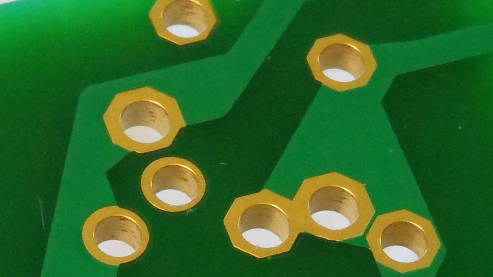
Context photo of plated-through holes on a separate circuit board by G1MFG, cropped and resized, CC BY-SA 4.0. The collaborators show their three prototypes in the original research report. Photo source · License.

The useful output is a design package a person can inspect
For the speakerphone, the collaborators started from a short request for a USB-C device with microphones, a speaker and Bluetooth. Claude translated that into requirements and worked through the schematic, component placement, copper routing, enclosure and firmware. It produced a parts list and instructions for assembly. Diode assembled the board and ran the firmware. Anthropic and Diode report that the prototype was still working after weeks of use. The duration describes this prototype under the team's use. It gives no population-wide reliability estimate. Speakerphone case
The design package is useful because each artifact exposes a different failure mode. A schematic makes the proposed electrical connections inspectable. A layout shows what happens when those connections must fit on a real board. A parts list lets the manufacturer check what it can source. Mechanical drawings and assembly instructions can reveal a problem that none of the electrical views would show. Firmware makes it possible for the person at the bench to check that the device actually responds to input.
That distinction helps explain why evaluating an AI-generated board differs from evaluating a polished 3D render. A beautiful enclosure cannot tell you whether a power rail has the right components or whether a connector is placed where a cable can reach it. A fully routed board can still interfere with the enclosure, and a fitting assembly can still reset unexpectedly under load. Each stage needs its own pass criterion. A useful package makes those criteria easier to apply before the next stage.
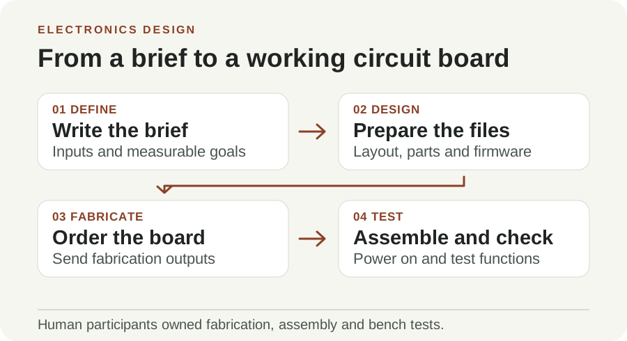
Original illustration by Telli.sh. The schematic, layout, assembly files and firmware each give a reviewer a different way to catch a problem.
The touch wheel made one layer decision affect the next
Printed circuit boards stack layers so many connections can fit in a small area. Tracks are the copper paths on a layer, and vias connect copper between layers. A model laying out the speakerphone had to accommodate a capacitive touch wheel whose electrodes occupied a region on the board. A hole drilled in the wrong spot could cut through that geometry. According to the November 9 report, Claude kept the relevant signal tracks under the touch wheel on a single layer and chose chip pin assignments that let those tracks avoid crossing. It also kept copper and holes away from the Bluetooth antenna region across the four layers. Speakerphone layer illustrations
Those decisions are related. Changing a pin assignment may free a route on the board, but the firmware must then agree with the new assignment. Moving an antenna region may help a layout fit, but it changes where metal can go and what the enclosure can place nearby. A reviewer gets more value from an explanation of what else had to change than from a drawing that merely has no unconnected lines.
The voice-assistant hub gave a second example. The team reports that Claude prioritized USB and Ethernet connections and used paired tracks with controlled geometry. It used tuning patterns where needed and placed grounded copper near high-speed routes to provide a return path. Those choices give an electrical engineer concrete things to inspect in the design. Measurements at the bench still determine whether the device meets its signal and emissions requirements. Voice hub case and layer views · KiCad PCB routing documentation
The mute switch exposed a different kind of geometry. A person might check the board in its final position inside the enclosure and conclude that everything fits. Assembly depends on the path the board takes to get there. The proposed tilt gives the technician a reproducible sequence, with a visible interference point if the sequence fails. The same reasoning can help with a connector that needs insertion clearance or a screw a tool cannot reach once another part is installed.
A manufacturable file has evidence a factory can check
The report describes two separate checks Claude ran. A design-for-manufacturing check compared the board geometry with the factory's constraints. A sourcing check established whether distributors could supply the proposed parts. Diode says the hub's checks flagged six thin regions of solder mask. Claude adjusted the mask openings without moving components. The report also describes an intentional ground connection that the automated checker flagged, which the team says the model correctly kept. These details show why a passing checklist and the reasoning behind exceptions both belong in the handoff. Manufacturing checks
Ask for those exceptions in a form a reviewer can revisit. The useful record includes the rule, the affected location, the reason the exception exists and the person who accepts it. A change made for a particular factory's rules may require another check if the job moves to a different manufacturer. If the layout, parts or assembly sequence changes after a check, attach the result to the earlier revision and run it again on the changed files.
Parts substitution needs similar care. A second component can fit the same footprint and still have different electrical characteristics, packaging details or firmware requirements. In a small pilot, a part approved for the original device and a proposed alternate should remain separate entries. The team can document why it accepts the substitution and which checks become relevant again. That record saves time when a distributor changes availability during a later build.
The benchmarks help explain where the model improved
Anthropic says Fable 5.2 scored 69% on Diode's internal PCB Gym evaluation, compared with 25% for Claude Fable 5. The benchmark removes layouts from existing boards and asks models to place components and reroute connections. Anthropic also reports 83.5 on a 0–100 scale with partial credit for Fable 5.2 on BenchCAD 2.1, which tests reconstruction of engineering objects from drawings and rendered images. Each score belongs to the task and protocol that produced it. A reader's board still needs its own validation, and factory yield requires production data. Benchmark descriptions and scores · BenchCAD scoring scale
The benchmarks and the working prototypes give different kinds of evidence. PCB Gym helps explain the reported progress in placement and routing under a controlled setup. The speakerphone adds a concrete example of the model accounting for the case, touch surface, parts and firmware together. Both are informative. A team trying this on its own design should look at the package its engineer can review and the measurements it can obtain on its bench.
| Milestone | Evidence it can provide | Example follow-up |
|---|---|---|
| Schematic and routing | The design files contain the proposed connectivity and physical layout | Review power paths, pin assignments and geometry against datasheets |
| Manufacturing checks | The build files meet specific checks for a chosen process | Resolve exceptions and verify that available parts match the approved bill of materials |
| Bench prototype | An assembled unit can perform a specified job under the observed setup | Record power behavior, firmware version and repeatability across cases |
| Product qualification | Results from defined tests across representative conditions and units | Plan electrical, thermal, radio or certification work with appropriate experts |
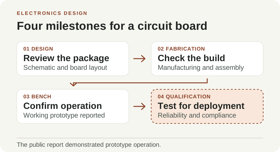
Original illustration by Telli.sh. The collaborators reported three working prototypes. Product qualification requires further testing.
Start with a low-voltage board and a measurable job
An approachable pilot is a USB-powered status indicator or a simple sensor breakout. A team might ask the model to draft the design files and define a measurable outcome, such as whether a button causes a firmware event in the expected order. That gives the engineer a small design to review without depending on a complicated radio, battery circuit or enclosure. An internal tool with an existing reference circuit can also make it easier to see how much of the design the model actually changed.
- Write down the operating assumptions. Specify the power source, connections, enclosure dimensions and expected behavior. List the applicable parts and factory rules before asking for a board.
- Ask for inspectable files. Request a schematic, a board file, a bill of materials and the firmware source. Ask the model to cite the datasheets and design rules behind consequential decisions.
- Have a qualified person review the release package. Run electrical and board rule checks with your design tool, examine the exceptions and check the parts and mechanical clearances. Compare the revision IDs before sending anything to a manufacturer.
- Bring up the board with controlled tests. A qualified engineer can check the board in an appropriate setup, inspect power behavior and run the intended firmware. Write down the conditions and results alongside the design revision.
- Record the next decision. Decide whether the artifact is a useful prototype, needs another revision or requires qualification. Feed only measured failures and documented changes into the next design round.
Plan for the case where the model asks a reasonable question and the team cannot answer it. A reference clock, enclosure material or permitted component family can change the design substantially. Answering that question early may save more time than letting a model infer the requirement and discovering the assumption after fabrication. If the model produces a finished package anyway, keep the inferred assumption in the review record and make the missing decision explicit before release.
Anthropic introduced Fable 5.2 and Mythos 5.2 on November 9. Fable was broadly available according to Anthropic's release, while Mythos access was limited to approved uses and organizations. The electronics research identifies Fable 5.2 as the model used for the prototypes. A team deciding whether to try the workflow should choose tools it can use with its existing design, data-handling and review requirements. Model announcement and access details
A working prototype makes the next test possible
The speakerphone's board had a specific way into the case, and someone could try it. That is a more useful kind of AI output than a general assurance that a design should work. When the next board arrives, the engineer needs the files, the assumptions and the measurements that make one conclusion defensible. A model earns its place in that process when the person at the bench can follow its work and learn where to look when reality disagrees.
Sources
- Anthropic and Diode electronics design report, November 9, 2026
- Claude Fable 5.2 and Mythos 5.2 release, November 9, 2026
- KiCad PCB Editor documentation
- Circuit-board photo by G1MFG, CC BY-SA 4.0
For a searchable record of the conversations and decisions behind your work, Create a Telli.sh account.