Can a Warehouse Robot Run Four Cameras Without Falling Behind?
AAEON's BOXER-8741AI brings Jetson Thor and multi-gigabit camera networking to an edge PC. Here is what a warehouse robot pilot should measure before rollout.
A warehouse robot can return a perfectly good detection from a frame it captured too long ago. By the time that result reaches the software guiding the robot toward a loading dock, the pallet in the frame may have shifted and a newer view may already be waiting in a queue. Adding cameras can improve coverage around the robot. It also gives the computer more images to receive, decode and process before any result is useful.
On November 12, 2026, industrial computer maker AAEON announced the BOXER-8741AI, an edge PC built around NVIDIA's Jetson Thor platform. Its mix of high-speed Ethernet and CAN FD makes it an interesting candidate for an autonomous mobile robot, or AMR, that needs several cameras and a connection to vehicle electronics. The practical question is how consistently the entire system can turn fresh frames into a useful observation while the robot is moving, recording video and sharing data with the rest of the operation. AAEON's November 12 announcement
What AAEON put in the box
AAEON makes industrial computers for applications where a machine builder has to plan for factors such as mounting, cabling and power alongside compute performance. AAEON's November 12 launch materials list the NVIDIA Jetson T5000 module with 128 GB of LPDDR5X memory, two 10-gigabit Ethernet ports, four 5-gigabit Ethernet ports and two CAN FD interfaces. That gives a team several ways to connect Ethernet cameras and pass data to other devices. A team could connect cameras directly where the camera and host support that arrangement, or bring a camera switch back to a faster uplink and keep the plant network on another interface. AAEON also publishes product photos showing the chassis and its connectors. AAEON launch specifications · AAEON official photo gallery
NVIDIA lists up to 2,070 sparse FP4 TFLOPS for the T5000. That figure describes peak processor performance under NVIDIA's stated precision and sparsity conditions. Camera ingest, video decoding, image conversion, inference, storage and application messaging each add work. An existing model may also use a different precision. The figure gives engineers a reference when comparing modules. The acceptance numbers for a robot come from running its own models, cameras and software together. NVIDIA Jetson module specifications
The interface list deserves a check before a purchase order. Earlier preliminary material and the AAEON Korea product listing show connectivity details that differ from the November 12 launch materials, including references to 25-gigabit Ethernet and QSFP. The documents are enough to flag a configuration question. They leave the hardware that a particular distributor would ship unsettled. Ask for a quote tied to an exact orderable part number, a connector diagram for that part and a delivery estimate for the region where the pilot will run. The public announcement establishes that AAEON introduced the system. Regional stock, lead times and pricing remain unverified. AAEON preliminary datasheet · AAEON Korea listing · AAEON global product page
Four cameras give you a bandwidth problem you can calculate
Suppose a robot approaching a pallet has a forward camera, two cameras covering its sides and a close-up camera for aligning at the station. As a planning exercise, give each camera an uncompressed 1,920 × 1,080 stream at 30 frames per second. With tightly packed 8-bit monochrome pixels, one stream carries about 0.50 Gb/s of image data. With tightly packed 24-bit RGB pixels, one stream carries about 1.49 Gb/s. Four RGB streams in that example add up to about 5.97 Gb/s before any overhead.
| Example capture format | One camera | Four cameras |
|---|---|---|
| 1,920 × 1,080 at 30 fps, 8-bit monochrome | 0.50 Gb/s | 1.99 Gb/s |
| 1,920 × 1,080 at 30 fps, 24-bit RGB | 1.49 Gb/s | 5.97 Gb/s |
Those are calculated image payload rates. Protocol overhead, other devices and short bursts add to the budget. Actual throughput on the BOXER-8741AI remains a pilot measurement. Check the planned pixel format on the actual camera. Bayer, YUV, packed RGB and compressed video can have different transport and processing costs. Compressed video can reduce network traffic, while its bit rate can vary with the scene and decoding may add delay. Even two cameras at the same advertised resolution may behave differently if one performs more processing before it sends each frame.
Follow the traffic through the whole diagram. If all four RGB feeds enter a switch with a single 5 Gb/s uplink, their example payload already exceeds that link's nominal rate. A 10 Gb/s uplink gives that particular example more room. The host still has to receive the frames, allocate buffers, do any format conversions and make data available to the model. If the same switch also carries fleet telemetry or video clips headed to a server, include that traffic in the calculation and test it on the intended topology. The value of separate ports is partly in being able to put a high-volume stream on a path where it has less to compete with.
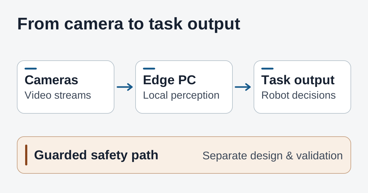
Camera and task data pass through the edge PC. Safety functions keep a separately validated path.
A stationary loading station illustrates another trade-off. A single close-up camera might need enough detail to read a worn label under variable lighting, while a wide-angle stream mainly helps establish that a pallet is in view. The cameras can run at different resolutions or frame rates. Keep what each view must resolve and how fresh it has to be in the requirements for that stream. Splitting the requirements can lower bandwidth and processing load without taking detail away from the one view that needs it.
Measure how old the frame is when the result arrives
Start with the outcome the operator can observe. A pallet approach may need the task controller to receive a current position estimate soon enough to decide whether to continue alignment. A perception stack reporting high frames per second can still deliver stale observations if it queues frames faster than it consumes them. Measure the interval from capture to the point where the task controller actually receives and accepts a result. That covers more of the work that determines the robot's behavior than an inference timer does.
Start with a repeatable route. Include the aisle, docking maneuver and lighting shifts the robot is likely to encounter, then preserve that route and its camera settings as a baseline for later comparisons.
- Make the timestamps comparable. Use a shared or calibrated timebase for capture, receipt and the controller event. Record where each timestamp comes from. A host's arrival time is useful for diagnosing the network, but if the camera queues or compresses a frame first, arrival time misses part of the wait.
- Log the slow cases and the missing cases. Save the median and 95th-percentile capture-to-result times, along with dropped frames, instances where the pipeline declined a stale frame, and periods when the controller received no fresh result. If a run drops its oldest frames, a report built only from frames that survived could make the run look quicker than it felt.
- Run the real combination of tasks. Stream every required camera together. Enable the intended model, local recording, fleet messages and uploads that will overlap on a normal shift. Log GPU, decoder, CPU, memory and storage activity so the team can see where queueing begins. Repeat a noisy stretch of the route with and without clip uploads to learn whether those transfers change the result.
- Repeat after the machine has warmed up. Use the intended enclosure, mounting and power setup. Record sustained input power and temperatures along with frame age and dropped connections. Test the route again after a long run and during expected network interruptions, then observe whether the system returns to normal without an operator restarting the application.
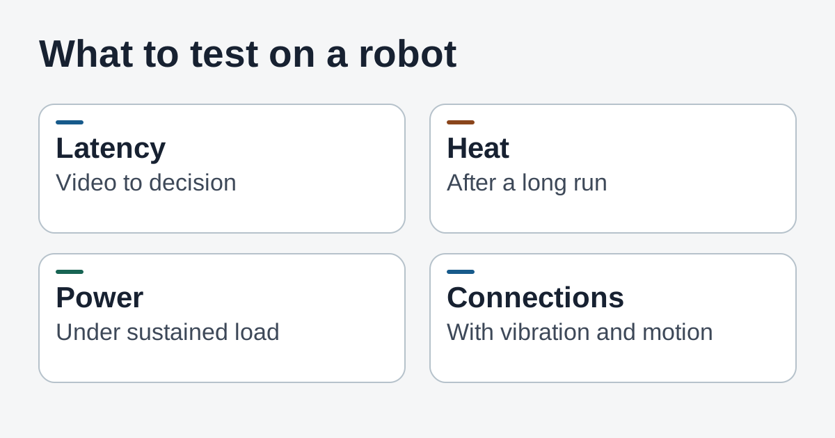
The robot's pilot data can reveal delay, heat, power and connection problems that are easy to miss when components are tested individually.
Agree on the acceptance criteria before comparing hardware. Use the current system's baseline and the task's need for fresh data to set them. For a pilot, it helps to capture both the time to a usable result and how often no usable result arrives in time. Record all the camera and software settings with those numbers. Change one condition per comparison so the results can show whether compressed capture, a different switch or a model build changed performance.
Keep perception and the safety decision separate
Perception can help estimate the pallet's position or tell the task software that an intended docking view is obstructed. A machine's safety functions, such as reacting to a safeguarding device or an emergency stop, have a separate design and validation process. A CAN FD connection can carry data between vehicle systems. The presence of the interface on a product sheet is evidence of connectivity. Safety certification and suitability depend on the components and architecture the integrator actually validates.
For an AMR pilot, agree with the controls and safety teams on what the task software will do with a lost camera connection, a stale observation or an edge PC restart. Capture that behavior during approved testing. Show what the operator sees and what conditions are required before normal task operation resumes. The controls team needs its own evidence that the robot's independent safeguards work as designed with the perception system unavailable.
That distinction is useful when comparing machines. If a more powerful edge PC recovers from camera interruptions faster, that may reduce time spent restarting an assisted docking task. The finding belongs to the task and recovery test. The independent safeguarding tests still have their own criteria.
What to take to an integration review
Bring the matching part-number quote, the camera topology with a traffic budget per link and a record of the exact system image and model build. Include camera and firmware versions, where the recordings go and how much work the robot has to do when the external network is temporarily unavailable. An example BOM is useful during planning. The test record should say which parts and software were physically present when the results were captured.
Set aside time for software and field service. A Jetson module can fit an existing development workflow, but the enclosure, camera drivers and operating system image determine which parts of that workflow carry over. In an integration trial, recreate the image from the team's documented versions, reconnect the sensors and check that the same capture formats and device assignments return after a restart. If the robot will be deployed in batches, try the process on a second unit. That helps an integrator learn which steps can be repeated and which still require someone familiar with the prototype.
Plan what operators will be able to see at the end of a shift. If a robot repeatedly loses the side camera after a particular turn, a log with camera identifiers, disconnect times and temperature readings gives field staff somewhere to start. An application dashboard that reports every stream as connected can still miss a feed whose last usable image is several seconds old. Consider displaying the last usable observation and the state of any interrupted task alongside basic link status. The pilot can then check whether the person supporting the route has enough information to handle the issue.
For the BOXER-8741AI, the case for a pilot is strongest when several high-bandwidth inputs and an existing Jetson software stack can benefit from a single industrial PC. The biggest open questions are the actual regional configuration and whether the full workload fits the robot's power, cooling and timing needs. A team with a single camera and a lightweight model can use the same acceptance process to see whether its current system already meets the task. For a four-camera pilot, the next practical input is a run of the complete workload in the intended installation.
Keep the pilot notes, camera diagrams and final settings together so the next test starts from the hardware and software that produced the numbers. Start your first note with Telli.sh.